This article is contributed by a netizen.
Author: Chen Xianda
Original Title: [Getting Started with Microcontrollers] (Part 4) Learning Microcontrollers from Application-Level Software Development: Using ESP32 Development Board PWM to Control Motors and Using Interrupts
Original Link: https://www.cnblogs.com/1996-Chinese-Chen/p/16846218.html
Introduction
Hello everyone, good evening. In the previous blog post, we discussed what UART serial communication is and how to use USB-to-TTL to enable serial communication between a microcontroller and a C# host computer. Next, I will introduce the concept and principles of PWM, along with a practical example of using PWM for motor speed control. Since the final project of this course is an infrared remote-controlled smart car, which requires four motors, four drivers, and four wheels, PWM is extremely important for the final outcome. In real-world development, PWM is also a commonly used speed control method.
Concept
PWM stands for Pulse Width Modulation. Its basic principle is to control the on/off of switching devices in an inverter circuit, producing a series of pulses with equal amplitude but varying widths at the output, which are used to replace sine waves or other desired waveforms. That is, multiple pulses are generated within half a cycle of the output waveform, making the equivalent voltage of each pulse a sine waveform, resulting in a smooth output with fewer low-order harmonics. By modulating the width of each pulse according to certain rules, both the output voltage of the inverter circuit and the output frequency can be changed.
The above explanation might be too official and hard to understand. In simpler terms, it means controlling the high and low levels of the circuit for electronic components. Over a period of time, high and low levels produce a waveform at the output, which we call a PWM waveform. We need to control the output waveform of PWM using code: how long the high level (power-on time) lasts within that period (the duty cycle), and how frequently the high and low levels switch within the PWM waveform. This introduces two concepts: Duty Ratio and Frequency. The duty ratio represents the proportion of time the high level is active relative to the total time (the duration of both high and low levels in the waveform), while frequency refers to the rate at which the high and low levels switch within the waveform.
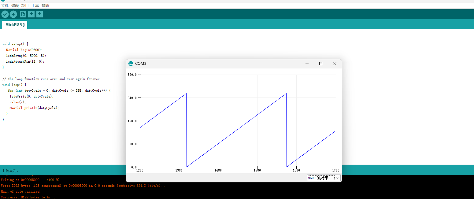
As shown in the figure below, the Arduino Serial Plotter displays a sawtooth waveform. In the GIF below, you can see the motor movement transitioning from fast to slow.

Code Analysis
void setup() {
Serial.begin(9600);
ledcSetup(0, 5000, 8);
ledcAttachPin(12, 0);
}
// the loop function runs over and over again forever
void loop() {
for (int dutyCycle = 0; dutyCycle <= 255; dutyCycle++) {
ledcWrite(0, dutyCycle);
delay(7);
Serial.println(dutyCycle);
}
}
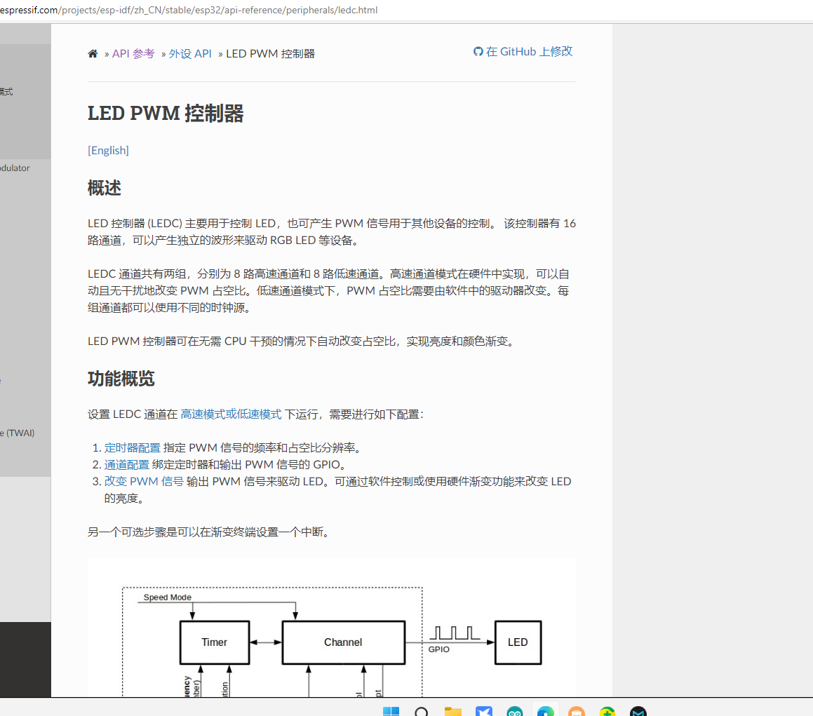
In Arduino, we can use the LEDC library to control PWM. On the pure C ESP32 development board, MCPWM can be used, but since Arduino does not support MCPWM here, LEDC serves as an alternative. The ESP32 has a 16-channel LED PWM controller, which uses Espressif's LED PWM control. The ESP32 LED PWM is divided into 8 high-speed channels and 8 low-speed channels. We use different frequencies and duty cycles to control the motor speed.
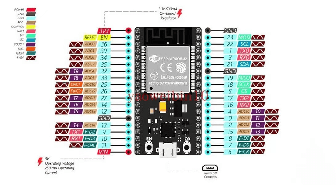
In the code above, we first set the LEDC channel to 0, the frequency to 5000, and use the 8th low-speed LED controller, i.e., ledcSetup(0, 5000, 8);. Then we associate the channel with a pin using ledcAttachPin(12, 0);, linking pin 12 to channel 0. In the loop code, we can see that the maximum duty cycle written is 255, with a total range of 0-255 (256 values). This is because the duty cycle is related to the channel. As mentioned earlier, the LED PWM controller has 16 channels. Here we use 8, and 256 is 2^8. Therefore, the maximum duty cycle is 256. If the value were 10, the maximum duty cycle would be 1024-1. ledcwrite(0, dutyCycle); writes the duty cycle to the corresponding channel, completing the PWM motor speed control setup.

Currently, the known Arduino wrapper for the ESP32's Espressif PWM is LEDC, which is available by default without installation. There are other PWM wrappers, but after testing one or two, none are as easy to use. Readers are welcome to explore other useful PWM libraries for development.
Interrupts
After discussing PWM, let's talk about interrupts and a practical interrupt example. An interrupt, as the name suggests, is a situation during program execution where, upon encountering an event, the current task is paused to handle that event first. This action—interrupting the current work to execute something else—is called an interrupt. Although you could register a background task (in pure C) with an infinite while loop, this is not performance-efficient for a microcontroller. Therefore, interrupts are used to achieve certain functions, such as using a button to decide whether to turn on an LED or perform other actions.
In Arduino, we can use the attachInterrupt function to add an interrupt to a pin and detachInterrupt to remove it.
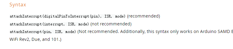
The attachInterrupt function requires three parameters: the first is the pin to be used for the interrupt, the second is the interrupt service routine (ISR), and the third is the interrupt mode. For the ESP32 in Arduino, the ISR function must be prefixed with IRAM_ATTR to mark it as an interrupt function. In the code below, digitalPinToInterrupt is used to bind pin 27 to an interrupt. Other methods exist, but they are not officially recommended.
In the code below, we define a function change to handle the interrupt on pin 27 of the ESP32. The pin 27 level controls the level of LED pin 2, thereby turning the LED on or off. First, set pin 2 as output and pin 27 as input with pull-up (INPUT_PULLUP). This mode is typically needed for pull-up resistors. Then we associate pin 27 with the interrupt, set the ISR to change, and the mode to CHANGE. In the loop function, we write the value of state to pin 2. When the change ISR is entered, state is toggled, and then loop writes the new value. This implements control of the LED (on/off). Here is a reminder: in microcontrollers, interrupts and timers are non-blocking, but Serial.println is a blocking write to the buffer. Using it in an ISR may cause continuous errors, such as: Guru Meditation Error: Core 1 panic'ed (Interrupt wdt timeout on CPU1).
This is because println blocks and prevents the timer from continuing. If you must use this function, consider setting an intermediate variable and checking its change in loop to output serial information.
In the GIF below, you can see us using a button to control the LED on/off.
volatile byte state = LOW;
void IRAM_ATTR change()
{
state=!state;
}
void setup() {
// put your setup code here, to run once:
Serial.begin(9600);
pinMode(2, OUTPUT);
pinMode(27, INPUT_PULLUP);
attachInterrupt(digitalPinToInterrupt(27), change, CHANGE);
}
void loop() {
digitalWrite(2, state);// put your main code here, to run repeatedly:
}
You can see the second method passes an interrupt number, but the interrupt numbers on the ESP32 are not documented in official materials. Therefore, we only need the first method to associate a pin with an ISR. Of course, the last method might also work, but I haven't tried it here; feel free to experiment.
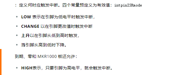
Regarding the mode, Arduino supports five modes. The first is LOW, which (as the name suggests) triggers the ISR when the pin is at a low level.
The second is CHANGE, which triggers on any change from high to low or low to high.
The third triggers when the pin transitions from low to high, not when it is already high.
The fourth is FALLING, which triggers when the pin goes from high to low.
The fifth is HIGH, which triggers when the pin is at a high level.


Conclusion
Today we covered PWM and the use of interrupts. It may be a lot to digest at once. If you have any questions, feel free to ask me. I will also slow down the update frequency a bit to prevent rushing through content. In the future, I will explain IIC and SPI with examples. After that, I will start working on the ultimate goal: building a smart car. I will list the required components and purchase links in the group within the next couple of days. If you are interested, you can join the QQ group to learn and discuss together. The author is also a beginner in microcontrollers and will later explore the STM32 series. Everyone is welcome to join the discussion and learning.